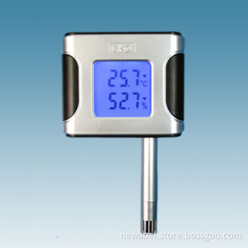
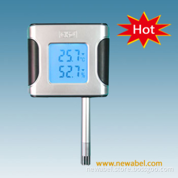
LCD, TCP/IP Digital Temperature & Humidity Sensor (CHD301C2-E)
- Payment Type:
- T/T, Western Union
Quantity:
Your message must be between 20 to 2000 characters
Contact NowBasic Info
Basic Info
| Place of Origin: | China |
|---|---|
| Payment Type: | T/T, Western Union |
Product Description
Product Description
LCD, TCP/IP Digital Temperature & Humidity Sensor
PARAMETER:
Size: 120mm x 206mm x 24mm
Working power supply: DC7V -DC20V, current: Less than 2.5Ma
Humidity measure bound: 10%-98%RH (precision: ± 3%RH)
Temperature measure bound: -10ºC-100ºC (precision: ± 0.4ºC)
Communication Interface: RS485 standard, RS232 or TCP/IP optional
LCD display, with background light button
Water-proof function protection
Installed with SCM (single chip) so that it can report mistakes automatically and will not lose data when power off
Unique design of connection lines for input and output ensures convenience in installation, many colors are optional.
Installation Steps
Method 1: Mount in the 86mm conjuction box reserved in the wall (preferred)
1) Arrange wire to 86mm conjuction box;
2) Open the sensor cover, connect communication wire and 12V power cable. It is better to unify cable color, for example, red conectted to power positive pole, black connected to power negative pole, green with A cable, green white with B cable. Covered with pyrocondensation tube;
3) Fix sensor in the middle of 86mm conjunction box with 2 screws;
4) Set communication address and mark it. Note that the same network address cannot repeat, otherwise, communication will fail due to collision;
5) Cover it after testing and approve it works well.
6) Finish installation.
Method 2: Directly mount in the wall or other plane.
1) Select installation place, generally 1.3m, drill wire hole (diameter 8 ~ 12cm) or wire slot; Drill fixed holes and fill with 6mm plastic plug for fixing;
2) Open sensor cover and hang main body on the wall.
3) Set communication address and mark it. Note that the same network address cannot repeat, otherwise, communication will fail due to collision;
4) Cover it after testing and approve it works well.
5) Finish installation.
Related Keywords
Related Keywords
You May Also Like
You May Also Like
-
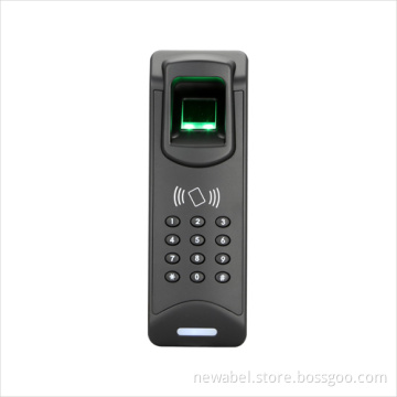
2015 New Fingerprint Reader
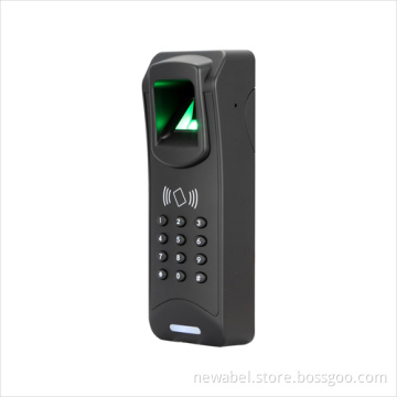
Keypad Password Fingerprint Reader

High Performance Finger Vein Reader
Related ProductsProduct Categories-
Car Parking System(17)
-
Access Control Management Series(18)
-
Intelligent Door Lock Series(21)
-
Smart Card Readers Series(18)
-
T Series Aceess Controller(11)
-
Accesories(9)
-
Biological Recognition Series(12)
-
Tripod turnstiles & Flap barrier gate(7)
-
Intelligent Sensor Series(4)
-
Elevaltor Controller Board(1)
-
Time Attendance Recorder Series(3)