8 Relay Output Ethernet Port Remote Controller
- Payment Type:
- L/C, T/T, D/P, Paypal, Money Gram, Western Union
Quantity:
Your message must be between 20 to 2000 characters
Contact NowBasic Info
Basic Info
| Place of Origin: | China. |
|---|---|
| Payment Type: | L/C, T/T, D/P, Paypal, Money Gram, Western Union |
Product Description
Product Description
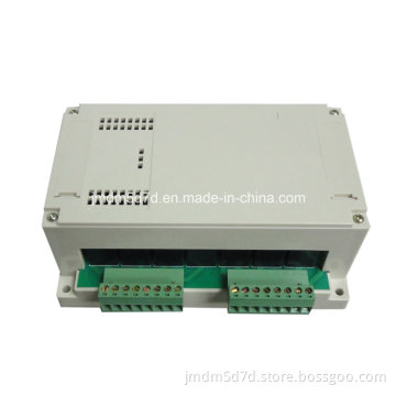
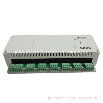
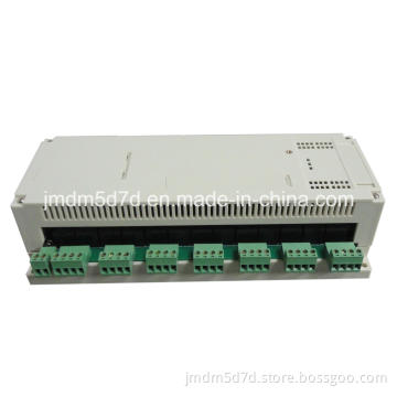
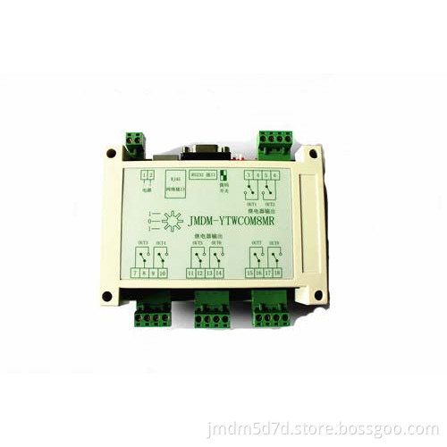
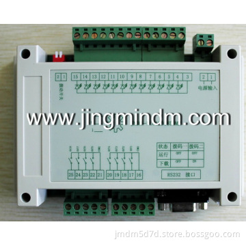
8 relay output Ethernet controller
Performance parameter:
1. Working power supply: DC12V-24V 1A; Control board with against lightning protection circuit, stable and reliable
2.32 bits high-performance single chip microcomputer control: Program storage space: 384K; Data storage space: 64k (if you have specific needs), save date, the date will not lost after power failure.
3. Two kind of communication interface:
1)1 channel RS232 interface, can be used to download the program and the upper computer communication.
2)1 channel RJ45 interface: The user according to their set of IP address and password, can be effective to external devices for remote control.
4. I/O:
8 channels relay output: Can effectively prevent the product on the instant when the electric misoperation, stable and reliable. Relay contact can withstand voltage AC 125 ~ 227v, the maximum output current is 10A-12A.
5. Program download instructions: Connect the serial communication line between computer and controller. Use MCU-ISP download software will be compiled HEX file downloaded to the controller. (note: The download process there is a manual process of power and electricity).
6. System stability: With industrial-grade lightning protection, strong resistance to electromagnetic interference, high reliability, no crash phenomenon.
7. Two working modes: Support independent control (according to the KEIL C language to write the program logic automatically control), RS45 network interface monitoring (need to write the upper and lower computer program);
8. Digital quantity working station indicator: Every channel digital output with an indicator light, convenient observation input or output points in working condition.
9. With FM24C02 ferroelectric memory EEPROM, date will not lost after power failure, user data can storage 128K.
10. Chip with embedded real time clock module, users according to the need for accurate setting (date) (month) (year) to make real time control.
11. With 2 dial switches, when downloaded the program for manual reset and run.
12. Shell size
Circuit board size: L*W*H: 122mm× 86mm× 23mm.
Shell size: L*W*H: : 145mm× 90mm× 40mm.
Mounting dimension: L*W: 135mm× 70mm.
Specification
1. Operating temperature: -40~+85° C;
2. Junction temperature: -40~+125° C;
3. Humidity: 5~95% no condensation
4. Power consumption (no external devices): + 12V @ 1A (typical value)
Usage:
In Windows XP or Windows 7 environment, Our company provide upper computer sample application and VC source code to the customer, the customer can be based on these for secondary development.
First supply control panel to power-on and connected to the controller and computer, then open the software, mouse the left key click the output button, visit websites and display web pages in the left window and information; Output as shown in the picture below, click on the "1", the button appears red (mouse out), so the corresponding light on control panel is the output point output. Again click on the "output" 1, button presented the computer color (mouse out), on the corresponding control panel lights off, output point stop output.
Click the same button again, button shows colorless, panel lights off.
As shown in the picture, click again on the output "1"
3. At the same time control 24 channel relay output control points of upper computer interface is as follows: Click the "all on" button, the button is all red, lights all on. Click the "all off" button, the button all show colorless, lights all off.
Attention:
1. Customer control panel will be in strict accordance with the wiring diagram connecting all finished, after checked can connect the power supply. Otherwise will burn out controller or external input/output devices.
2. Controller input signal is default the external DC 12 or 24V power supply.
Related Keywords
Related Keywords
You May Also Like
You May Also Like
-
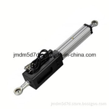
Stable and Reliable Electric Linear Actuator
Stable and Reliable Ab PLC Control Panel of Replacement
Stable and Reliable Schneider PLC Control Panel of Replacement
Stable and Reliable Schneider PLC Controller of Replacement
Stable and Reliable Schneider PLC Control Board of Replacement
Related ProductsProduct Categories-
parts(2)
-
9D cinema(5)
-
Simulator(32)
-
7D cinema(15)
-
5D cinema(32)
-
control system(32)
-
cinema parts(18)
-
special effects machine(3)
-
3D Cinema theater controller(11)
-
PLC controller(32)
-
Wireless remote controller(16)
-
Ethernet(Lan) controller(17)
-
Analog controller(13)
-
motion controller(17)
-
IO controller(32)
-
Voice controller(3)
-
Adjustable light power surge controller(4)
-
Other controller(11)