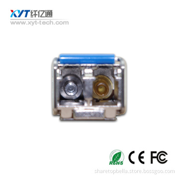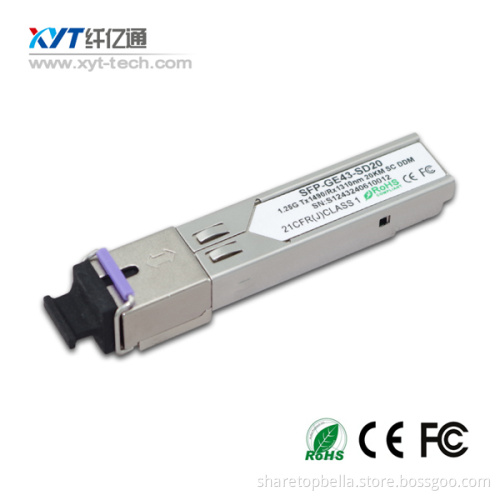
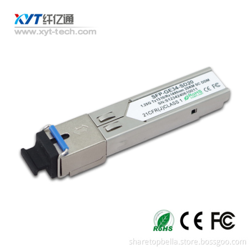
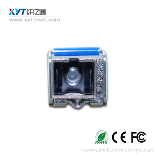

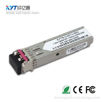
1000BASE-T and 10/100/1000BASE-T Copper SFP Transceiver
Your message must be between 20 to 2000 characters
Contact NowDescription
1.25 Gigabit Copper SFP Transceiver Small Form Pluggable (SFP)transceivers is high performance, cost effective module compliant with the Gigabit Ethernet and 1000BASE-T standards as specified in IEEE 802. 3-2002 and IEEE 802.3ab, which supp- orting 1000Mbps data- rate up to 100 meters reach over unshielded twisted-pair category 5 cable. The module supports1000 Mbps full duplex data-links with 5-level Pulse Amplitude Modulation (PAM) signals. All four pairs in the cable are used with symbol rate at 250Mbps on each pair. The module provides standard serial ID information compliant with SFP MSA, which can be accessed with address of A0h via the 2wire serial CMOS EEPROM protocol. The physical IC can also be accessed via 2wire serial bus at address ACh.
Features
1.Up to 1.25Gb/s bi-directional data links
2.Hot-pluggable SFP footprint
3.TX Disable and RX Los/without Los function
4.Extended case temperature range (0°C to +70°C )
5.Fully metallic enclosure for low EMI
6.Low power dissipation (1.05 W typical)
7.Compact RJ-45 connector assembly
8.Access to physical layer IC via 2-wire serial bus
9.1000 BASE-T operation in host systems with SERDES interface
10.10/100/1000Mbps compliant in host systems with SGMII interface
Applications
1.25 Gigabit Ethernet over Cat 5 cable
Table 1 - Optical and Electrical Characteristics
|
Pin |
Signal Name |
Description |
Plug Seq. |
Notes |
|
1 |
VEET |
Transmitter Ground |
1 |
|
|
2 |
TX FAULT |
Transmitter Fault Indication |
3 |
Note1 |
|
3 |
TX DISABLE |
Transmitter Disable |
3 |
Note2 |
|
4 |
MOD_DEF(2) |
SDA Serial Data Signal |
3 |
Note3 |
|
5 |
MOD_DEF(1) |
SCL Serial Clock Signal |
3 |
Note3 |
|
6 |
MOD_DEF(0) |
TTL Low |
3 |
Note3 |
|
7 |
Rate Select |
Not Connected |
3 |
|
|
8 |
LOS |
Loss of Signal |
3 |
Note 4 |
|
9 |
VEER |
Receiver ground |
1 |
|
|
10 |
VEER |
Receiver ground |
1 |
|
|
11 |
VEER |
Receiver ground |
1 |
|
|
12 |
RX- |
Inv. Received Data Out |
3 |
Note 5 |
|
13 |
RX+ |
Received Data Out |
3 |
Note 5 |
|
14 |
VEER |
Receiver ground |
1 |
|
|
15 |
VCCR |
Receiver Power Supply |
2 |
|
|
16 |
VCCT |
Transmitter Power Supply |
2 |
|
|
17 |
VEET |
Transmitter Ground |
1 |
|
|
18 |
TX+ |
Transmit Data In |
3 |
Note 6 |
|
19 |
TX- |
Inv. Transmit Data In |
3 |
Note 6 |
|
20 |
VEET |
Transmitter Ground |
1 |
|
Notes:
Plug Seq.: Pin engagement sequence during hot plugging.
1) TX Fault is not supported and is always connected to ground.
2) TX Disable is an input that is used to shut down the transmitter optical output. It is pulled up within the module with a 4.7 ¨C 10 K resistor. Its states are:
Low (0 to 0.8V): Transmitter on
(>0.8, < 2.0V): Undefined
High (2.0 to 3.465V): Transmitter Disabled
Open: Transmitter Disabled
3) Mod-Def 0,1,2. These are the module definition pins. They should be pulled up with a 4.7K to 10K resistor on the host board. The pull-up voltage shall be VccT or VccR
Mod-Def 0 is grounded by the module to indicate that the module is present
Mod-Def 1 is the clock line of two wire serial interface for serial ID
Mod-Def 2 is the data line of two wire serial interface for serial ID
4) LOS is an open collector output, which should be pulled up with a 4.7k~10kΩ resistor. Pull up voltage between 2.0V and Vcc+0.3V. Logic 1 indicates loss of signal; Logic 0 indicates normal operation. In the low state, the output will be pulled to less than 0.8V.
5) RD-/+: These are the differential receiver outputs. They are AC-coupled, differential lines with 100 differential termination inside the module.
6) TD-/+: These are the differential transmitter inputs. They are AC-coupled, differential lines with 100 differential termination inside the module.

Related Keywords