


Led display receiving card A4s Model
- Payment Type:
- L/C, T/T, Paypal, Money Gram, Western Union
- Incoterm:
- FOB, CFR, CIF
- Delivery Time:
- 15-30 Days
- Transportation:
- Ocean, Land, Air
- Port:
- Shenzhen, Hongkong, China
Your message must be between 20 to 2000 characters
Contact Now| Place of Origin: | CHINA |
|---|---|
| Productivity: | 1500 square meter/month |
| Supply Ability: | 1000 square meter/month |
| Payment Type: | L/C,T/T,Paypal,Money Gram,Western Union |
| Incoterm: | FOB,CFR,CIF |
| Certificate: | CCC,CE,UL,RoHS,FCC |
| HS Code: | 8528591090 |
| Transportation: | Ocean,Land,Air |
| Port: | Shenzhen,Hongkong,China |
Led display receiving card A4s Model
Product Feature:Led display receiving card
A4s Model
3.1 Improvement in Display Effect
Features
Description
Supporting pixel level brightness
and chroma calibration
Working with NovaLCT and NovaCLB,
A4s supports brightness and chroma calibration on each pixel.
Supporting image rotation in 90° increments
(Calibration not supported after
rotation)
On NovaLCT, the image on the
screen can be set to rotate in the multiples of 90° (90°,
180°, 270° and 360°).
Supporting quick seam correction
Working with NovaLCT, A4s supports
quick adjustment of bright and dark lines, which can remove the seams between
modules and between cabinets.
Supporting 3D function
On NovaLCT or operation panel of
controllers which support 3D function, you can enable 3D function and set the
3D parameters to make the LED screen display 3D effects.
3.2 Improvement in Maintainability
Features
Description
Supporting the smart module
(Supported by dedicated firmware
program)
The smart module is composed of
Flash and MCU.
Flash could store calibration
coefficients and module information. MCU could communicate with the receiving
card to realize monitoring over temperature, voltage and wiring communication
status for the module. Working with the driver chip, A4s supports open
circuit detection on LED.
The smart module could make
monitoring unit smaller, requiring no independent monitoring card
Receiving Card A4s
Features
Description
and saving cabinet space.
Supporting LVDS transmission
(Supported by dedicated firmware
program)
The transmission mode of
low-voltage differential signaling (LVDS) is used, which reduces the number
of data cables that connect the receiving card's HUB board to the module,
increases the transmission distance, improves the signal transmission
quality, and better stabilizes the image output.
Supporting setting of images
pre-stored of the receiving card
On NovaLCT, the specified images
could be set as the screen startup image and images used when the Ethernet
cable is disconnected or no video source signal is available.
Supporting module Flash management
On NovaLCT, lamp panel Flash could
be managed.
Supporting monitoring voltage and
temperature of itself
The voltage and temperature of the
receiving card itself can be monitored without using other peripherals. The
monitoring data can be checked on NovaLCT.
Supporting LCD module
Supports NovaStar's general 5-pin
LCD module. The LCD module is connected to the HUB board to display
temperature, voltage, single operating time and total operating time of the
receiving card.
Support one-click application of
calibration coefficient in module Flash
In the event of network outage,
hold down the self- test button to read the calibration coefficient in module
Flash back to the receiving card.
3.3 Improvement in Hardware
Reliability
Features
Description
Supporting dual-power backup
detection
Two power supplies could be
simultaneously connected, and operating status of the power supplies could be
detected.
Supporting loop backup
HUB`s Ethernet port improves the
reliability for the serial connection of the receiving card through main and
standby redundant mechanism. Among the main and standby serial connection
lines, if one fails, the other will begin to work to ensure the normal
operation of the display.
Receiving Card A4s
3.4 Improvement in Software
Reliability
Features
Description
Supporting readback of firmware
version
On NovaLCT, the firmware versions
of the receiving card can be read back.
Supporting readback of
configuration file
Specifications 3
Features
Specifications 3
Features
|
Product Image |


|
Product Parameters |
4.1 Appearance
Product images provided in this file are for reference only, and the actual products shall prevail.
Models of the high-density receptacle and plug used by A4s are shown in Table 4-1. Table 4-1 Model of high-density connector
4.2 Dimensions
Board thickness is not greater than 2.0 mm, and the total thickness (board thickness + thickness of both front panel and back panel) is not greater than 7.5 mm.
Unit of the dimension chart is [mm". Ground connection is enabled for location hole (GND).
|
Type |
Brand |
Material Code |
|
Receptacle |
Amphenol FCI |
10140609-121802LF |
|
PLUG |
Amphenol FCI |
10140607-121802LF |
Receiving Card A4s
Specifications 4
Hardware
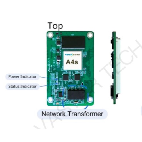
4.3 Indicators
|
Indicator |
Status |
Description |
|
Status indicator (green) |
Flashing every other 1s. |
The receiving card works normally, Ethernet cable connection is normal, and video source input is available. |
|
Flashing every other 3s. |
The receiving card works normally, while the Ethernet cable connection is abnormal. |
|
|
Rapidly flashing for 3 times every other 3s. |
The receiving card works normally, Ethernet cable connection is normal, while no video source input is available. |
|
|
Rapidly flashing every other 0.5s. |
Program loading fails in normal operating state, coming to the backup operating state. |
|
|
Rapidly flashing for 8 times every other 1s. |
The receiving card is in the Ethernet port backup status and the backup is effective. |
|
|
Power indicator (red) |
Always on |
It is always on after the power is on. |
Receiving Card A4s Specifications
4.4 Definition of Data Interface ( Top ) 4.4.1 24-Group Parallel Data
4 Hardware
|
JH1 |
|||||||
|
GND |
1 |
H1 2 |
GND |
||||
|
LCD |
CS signal of LCD |
EXT_LCD_CS |
3 |
4 |
NC |
||
|
RS signal of LCD |
EXT_LCD_RS |
5 |
6 |
NC |
|||
|
Clock signal of LCD |
EXT_LCD_SCL |
7 |
8 |
NC |
|||
|
Data signal of LCD |
EXT_LCD_SDA |
9 |
10 |
NC |
|||
|
Backlight signal 1 of LCD |
EXT_LCD_BL0 |
11 |
12 |
NC |
|||
J
Receiving Card A4s Specifications
4 Hardware
Note 4
Note 4
Note 4
Note 1
/ RFU4 / RFU6 / RFU8 / RFU10 / RFU12 / RFU14
83 84 RFU3 / 85 86 RFU5 / 87 88 RFU7 / 89 90 RFU9 / 91 92 RFU11 / 93 94 RFU13 /
Note 4
Note 4
Note 1
9
Backlight signal 2 of LCD
LCD control button /
/
/ / / / / /
/ / / / / /
JH1 JH1
EXT_LCD_BL1
EXT_KEY RFU11718NC RFU21920NC
GND 21 22 NC NC 2324 NC GND 25 26 GND
G172728R17 / R182930B17 / B183132G18 / G193334R19 / R203536B19 / B203738G20 /
GND 39 40 GND G214142R21 / R224344B21 / B224546G22 / G234748R23 / R244950B23 / B245152G24 /
GND 53 54 GND NC 5556 NC NC 5758 NC NC 5960 NC NC 6162 NC NC 6364 NC NC 6566 NC GND 67 68 GND NC 5556 NC NC 5758 NC NC 5960 NC NC 6162 NC NC 6364 NC NC 6566 NC GND 81 82 GND
13 14 NC
15 16 NC
GND 95 96 GND
/ RFU16 / RFU18
NC 103 104 NC NC 105 106 NC NC 107 108 NC GND 109 110 GND GND 111 112 GND NC 113 114 NC VCC 115 116 VCC VCC 117 118 VCC VCC 119 120 VCC
97 98 RFU15 /
99 100 RFU17 / NC 101 102 NC
Receiving Card A4s Specifications
4 Hardware
Gigabit Ethernet port
Port2_T0+ Port2_T0- NC Port2_T1+ Port2_T1- NC Port2_T2+ Port2_T2- NC Port2_T3+ Port2_T3- NC NC
STA_LED-
GND DCLK
DCLK_2
LAT
CTRL
GND 65 66 GND G56768R5 R66970B5 B67172G6 G77374R7 R87576B7 B87778G8 GND 79 80 GND G98182R9
R108384B9 B108586G10 G118788R11 R128990B11 B129192G12 GND 93 94 GND G139596R13 R149798B13
Gigabit Ethernet port
Note 2
Note 3
Line coding signal A Line coding signal B
Line coding signal C
Line coding signal D
Line coding signal E Display enabled OE_BLUE
39 40 41 42
43 44
45 46
47 48 49 50
OE_RED OE_GREEN GND
Note 3
10
Shield grounding Eth_Shield 1 2 Shield grounding Eth_Shield 3 4
Eth_Shield
Shield grounding Shield grounding
/ /
/ /
/ /
/ /
Operating indicator
Shift clock output in the first route
Shift clock output in the second route
Locking of the signal output
Afterglow control signal Display enabled Display enabled
/ / / / / /
/ / / / / /
/ / / / / /
/ / / /
NC 7 / Port1_T0+ 9
/ Port1_T3+ / Port1_T3-
27 28
Test button TEST_INPUT_ KEY
/ / / / / /
/ / / / / /
/ / / / / /
/ / / /
B14 G15
99 100 G14 101 102 R15
NC 5
Eth_Shield 6 NC
8 NC
10 / Port1_T0- 11 12 NC 1314
- / Port1_T1+ 15 16
- / Port1_T1- 17 18
NC 19 20
- / Port1_T2+ 21 22
- / Port1_T2- 23 24
NC 2526
29 30 NC 3132 NC 3334
35 36 GND 37 38
GND 51 G15354R1 R25556B1 B25758G2 G35960R3 R46162B3 B46364G4
52
JH2
Receiving Card A4s
Specifications 4
Hardware
|
JH2 |
|||||||
|
/ |
R16 |
103 |
104 |
B15 |
/ |
||
|
/ |
B16 |
105 |
106 |
G16 |
/ |
||
|
GND |
107 |
108 |
GND |
||||
|
NC |
109 |
110 |
NC |
||||
|
NC |
111 |
112 |
NC |
||||
|
NC |
113 |
114 |
NC |
||||
|
NC |
115 |
116 |
NC |
||||
|
GND |
117 |
118 |
GND |
||||
|
GND |
119 |
120 |
GND |
||||
4.4.2 64-Group Serial Data
|
JH1 |
|||||||
|
GND |
1 |
2 |
GND |
||||
|
LCD |
CS signal of LCD |
EXT_LCD_CS |
3 |
4 |
NC |
||
|
RS signal of LCD |
EXT_LCD_RS |
5 |
6 |
NC |
|||
Receiving Card A4s
Specifications 4
Hardware
|
JH2 |
|||||||
|
/ |
Data36 |
91 |
92 |
Data35 |
/ |
||
|
GND |
93 |
94 |
GND |
||||
|
/ |
Data38 |
95 |
96 |
Data37 |
/ |
||
|
/ |
Data40 |
97 |
98 |
Data39 |
/ |
||
|
/ |
Data42 |
99 |
100 |
Data41 |
/ |
||
|
/ |
Data44 |
101 |
102 |
Data43 |
/ |
||
|
/ |
Data46 |
103 |
104 |
Data45 |
/ |
||
|
/ |
Data48 |
105 |
106 |
Data47 |
/ |
||
|
GND |
107 |
108 |
GND |
||||
|
NC |
109 |
110 |
NC |
||||
|
NC |
111 |
112 |
NC |
||||
|
NC |
113 |
114 |
NC |
||||
|
NC |
115 |
116 |
NC |
||||
|
GND |
117 |
118 |
GND |
||||
|
GND |
119 |
120 |
GND |
||||
Note 1. Voltage ranging from 3.3V to 5.5V is recommended for input power (VCC).
Note2. Operatingindicatorthatmeetslowlevelisvalid.
Note 3. OE_RED, OE_GREEN and OE_BLUE are display enabled pins. In case that OE_RGB are not controlled separately, OE_RED is applied. While PWM chip is used, GCLK signal is enabled.
Note 4. RFU1–18 are the reserved extended function interfaces. Please refer to [4.4.3 Extended Functions Design".
4.4.3 Extended Functions Design
|
Extended Functions Description |
|||
|
Expandable Interface |
Recommended Smart Module Interface |
Recommended Module Flash Interface |
Description |
|
RFU1 |
Reserved |
Reserved |
Reserved pin that connects to MCU |
|
RFU2 |
Reserved |
Reserved |
Reserved pin that connects to MCU |
|
RFU3 |
HUB_CODE0 |
HUB_CODE0 |
Flash control interface 1 |
|
RFU4 |
HUB_SPI_CLK |
HUB_SPI_CLK |
Clock signal of the serial interface |
|
RFU5 |
HUB_CODE1 |
HUB_CODE1 |
Flash control interface 2 |
|
RFU6 |
HUB_SPI_CS |
HUB_SPI_CS |
CS signal of the serial interface |
|
RFU7 |
HUB_CODE2 |
HUB_CODE2 |
Flash control interface 3 |
|
RFU8 |
/ |
HUB_SPI_MOSI |
Module Flash storage data input |
|
HUB_UART_TX |
/ |
TX signal of the smart module |
|
|
RFU9 |
HUB_CODE3 |
HUB_CODE3 |
Flash control interface 4 |
|
RFU10 |
/ |
HUB_SPI_MISO |
Module Flash storage data output |
|
HUB_UART_RX |
/ |
RX signal of the smart module |
|
|
RFU11 |
HUB_H164_CSD |
HUB_H164_CSD |
74HC164 data signal |
|
RFU12 |
/ |
/ |
/ |
|
RFU13 |
HUB_H164_CLK |
HUB_H164_CLK |
74HC164 Clock signal |
|
RFU14 |
POWER_STA1 |
POWER_STA1 |
1Dual-power detection signal 1 |
|
RFU15 |
MS_DATA |
MS_DATA |
Dual-card backup connection signal |
|
RFU16 |
POWER_STA2 |
POWER_STA2 |
2Dual-power detection signal 2 |
|
RFU17 |
MS_ID |
MS_ID |
Dual-card backup identification signal |
Receiving Card A4s
Specifications 4
Hardware
Note: The RFU8 and RFU10 are signal multiplex extension interfaces. You can select only one interface from either the Recommended Smart Module Interface or the Recommended Module Flash Interface at the same time.
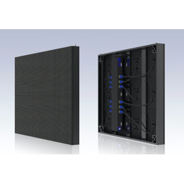
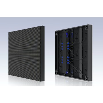
|
Package case |


|
Our Service |
1. Best price: We can offer you the best competitive price with the same even better quality. Mostly depends on the quantity.
2. Best after sale service: We can response in time if customers have questions about the installation , usage and maintenance ect.
3. Your inquiry will be replied by well-trained and experienced staffs in 24 hours.
4. Top Quality+Reasonable Price+Responsible After Service=Successful & Win
5. Help you design OEM&ODM or any your customized lightings and put into production.
6. Distributorship are offered for your unique design and some our current models
7.Your sales area, ideas of design and all your private information will be well protected
Looking for ideal High Quality Led display receiving card A4S Model Manufacturer & supplier ?
---We have a wide selection at great prices to help you get creative ideas. All the Big Outdoor Advertising Screen are quality guaranteed.
---We are China Original Factory of Led display receiving card A4S Model. If you have any question, please feel free to contact us.
Product Categories : Outdoor Full Color Advertising LED Display, Outdoor Single red Color Advertising LED Display,
Wall hanging LED Display, Showcase LED Display, Cross LED Display, Double sided LED Display,
LED Light box, Fine pixel pitch LED Display, Rental LED Display, LED Curtain Display.
Related Keywords


