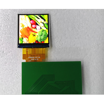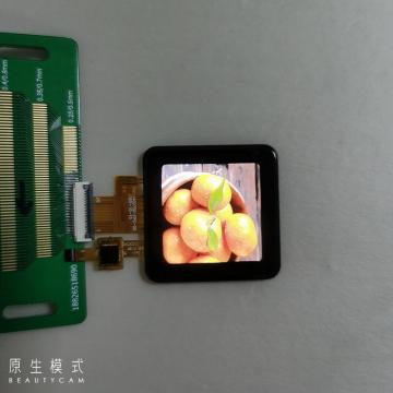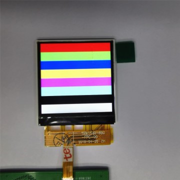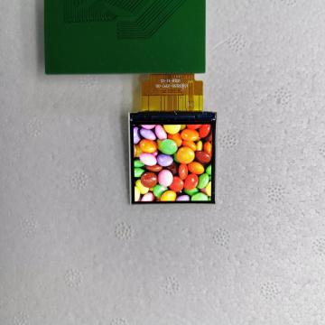
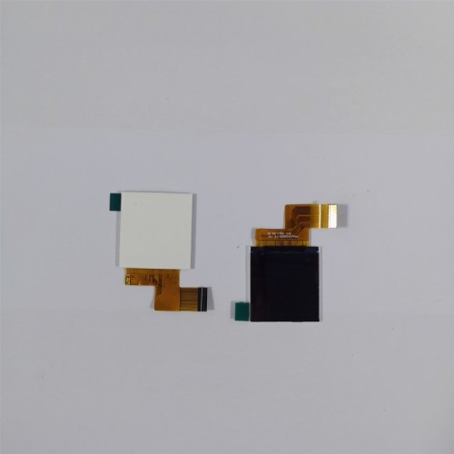
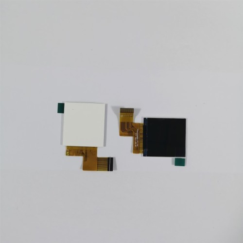
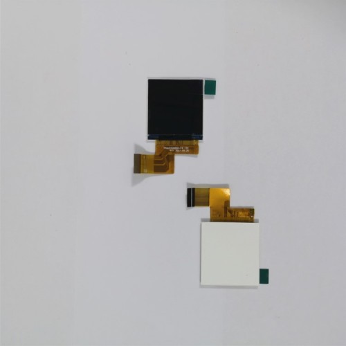
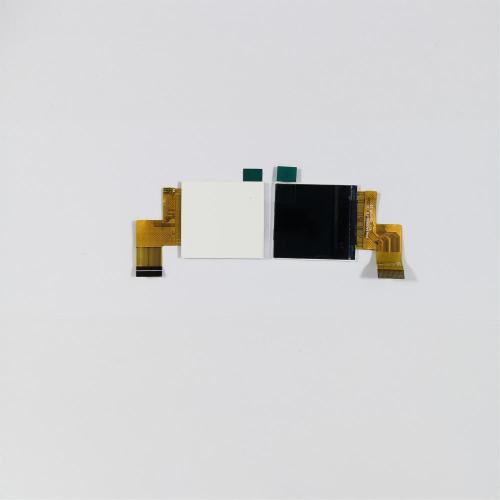
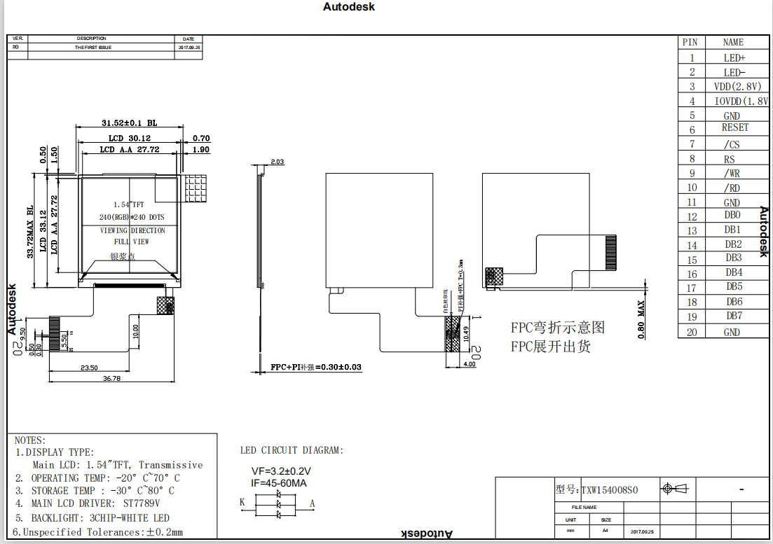
1.54 Inch LCD Display
- Payment Type:
- T/T
Your message must be between 20 to 2000 characters
Contact Now| Payment Type: | T/T |
|---|
A thin-film-transistor liquid-crystal display (TFT LCD) is a variant of a liquid-crystal display (LCD) that uses thin-film-transistor (TFT) technology to improve image qualities such as addressability and contrast. A TFT LCD is an active matrix LCD, in contrast to passive matrix LCDs or simple, direct-driven[clarification needed] LCDs with a few segments.
TFT LCDs are used in appliances including television sets, computer monitors, mobile phones, handheld devices, video game systems, personal digital assistants, navigation systems, projectors, and car dashboards.


1. Introduction
1.1 Scope of application
This specification applies to the LCD module that is supplied by
TIAN XIAN WEI TECHNOLOGY CO., LTD.
LCD specification: Dots 240xRGBx240
As to basic specification of the driver IC, refer to the IC (Sitronix:ST7789V)
specification and data book.
All material & processing of the LCD module should be Lead Free.
1.2 TFT features:
Structure: TFT PANNEL+IC +FPC+BL;
IPS Type LCD
240 dot-segment and 240 dot-common outputs;
65K Color can be selected by software;
White LED back light;
MCU-8bit interface
1.3 Applications:
Pos
Pda
Electronic cigarettes
Law enforcement equipment,
walkie-talkie,
household appliances
2. LCM General specification
|
ITEM |
Sandard value |
Unit |
|
LCD Type |
Normally black |
-- |
|
Drive element |
TFT active matrix |
-- |
|
Number of pixels |
240*3RGB(H)X240 (V) |
Dots |
|
Pixel arrangement |
RGB stripe |
-- |
|
Pixel Pitch (W*H) |
0.153(H) x0.153 (V) |
mm |
|
Active area |
27.72(H) x 27.72(V) |
mm |
|
Module Size(W*H*T) |
31.52(H) x33.72(V) x 2.03(D) |
- |
|
Viewing direction |
ALL O’CLOCK |
|
|
TFT Driver IC |
ST7789V |
- |
|
TFT interface |
MCU_8BIT Interface |
- |
|
Approx. Weight |
TBD |
g |
3.Absolute Maximum Rating
|
Characteristics |
Symbol |
Min. |
Max. |
Unit |
|
LCM Operating Temperature |
TOPR |
-20 |
+70 |
°C |
|
LCM Storage Temperature |
TSTG |
-30 |
+80 |
°C |
|
TP Operating Temperature & Humidity(20% ~ 90%RH) |
TOPR |
|
|
°C |
|
TP SStorage Temperature & Humidity(20% ~ 90%RH) |
TSTG |
|
|
°C |
|
Humidity |
RH |
- |
90 |
% |
4.Electrical Characteristics
4.1 TFT DC Characteristics
|
Characteristics |
Symbol |
Min. |
Typ. |
Max. |
Unit |
|
Supply Voltage for I/O |
VDDIO |
1.65 |
1.8 |
3.3 |
V |
|
Supply Voltage for(DC/DC) |
VDD |
2.7 |
2.8 |
3.3 |
V |
|
Supply Voltage for(DC/DC) |
AVDD |
|
|
|
V |
|
Supply Voltage for(DC/DC) |
AVEE |
|
|
|
V |
|
Current Consumption |
IDD |
- |
TBD |
- |
mA |
|
IDD-SLEEP |
|
TBD |
|
uA |
4.2Back-Light Unit Characeristics
The back-light system is an edge-lighting type with 3 white LEDs. The characteristics of the back-light are shown in the following tables.
|
Characteristics |
Symbol |
Min. |
Type |
Max. |
Unit |
Notes |
|
Forward Voltage |
VF |
2.9 |
- |
3.2 |
V |
- |
|
Forward current |
IF |
45 |
|
60 |
mA |
- |
|
Luminance(With LCD) |
Lv |
|
450 |
|
cd/m2 |
- |
|
LED life time |
N/A |
---- |
30,000 |
-- |
Hr |
Note 1 |
Note:
(1) The “LED life time” is defined as the module brightness decrease to 50% of original brightness at IL=20mA/LED. The LED life time could be decreased if operating IL is larger than 25mA/LED.
Backlight circuit diagram shown in below:
5. Module Function Description
5.1 LCM Pin Descriptions
|
Pin No. |
Symbol |
Description |
|
1 |
LEDA |
BACKLIGHT + |
|
2 |
LEDK |
BACKLIGHT- |
|
3 |
VCI |
POWER SUPPLY(2.8V) |
|
4 |
IOVCC |
DIGITAL VOLTAGE.( 1.8V/2.8v) |
|
5 |
GND |
GROUND |
|
6 |
RESET |
Hardware reset |
|
7 |
CS |
Chip select |
|
8 |
RS |
Register select input pin |
|
9 |
WR |
Write enable clock input pin |
|
10 |
RD |
Read enable clock input pin |
|
11 |
GND |
GROUND |
|
12-20 |
DB0~ DB7 |
Parallel data I/O. |
6. Timing Characteristics
7.Optical Characteristics
|
Items |
Symbol |
Condition |
Specifications |
Unit |
All left side data are based on TIAN XIAN WEI product reference only |
|||
|
Min. |
Typ. |
Max. |
||||||
|
Contrast Ratio |
CR |
|
640 |
800 |
- |
- |
||
|
Response Time |
TBRB |
- |
16 |
21 |
ms |
|||
|
TBFB |
- |
19 |
24 |
ms |
||||
|
Chromaticity |
Red |
XBRB |
|
/ |
|
- |
||
|
YBRB |
|
/ |
|
- |
||||
|
Green |
XBGB |
|
/ |
|
- |
|||
|
YBGB |
|
/ |
|
- |
||||
|
Blue |
XBBB |
|
/ |
|
- |
|||
|
YBBB |
|
/ |
|
- |
||||
|
White |
XBWB |
0.28 |
0.31 |
0.34 |
- |
|||
|
YBWB |
0.29 |
0.32 |
0.35 |
- |
||||
|
Viewing angle |
Hor. |
f1(3 o’clock) |
Center CR≥10 |
- |
80 |
- |
deg. |
|
|
f2(9 o’clock) |
- |
80 |
- |
|||||
|
Ver. |
q2(12 o’clock) |
- |
80 |
- |
||||
|
q1(6 o’clock) |
- |
80 |
- |
|||||
|
Uniformity |
|
|
|
|
--- |
|
% |
|
Note 1: Definition of Contrast Ratio (CR):
The contrast ratio can be calculated by the following expression.
Contrast Ratio (CR) = L63 / L0
L63: Luminance of gray level 63
L0: Luminance of gray level 0
CR = CR (10)
CR (X) is corresponding to the Contrast Ratio of the point X at Figure in Note 5.
Note 2: Definition of Response Time (TR, TF):
Note 3: Viewing Angle
The above “Viewing Angle” is the measuring position with Largest Contrast Ratio; not for good
image quality. View Direction for good image quality is 6 O’clock. Module maker can increase
the “Viewing Angle” by applying Wide View Film.
Note 4: Measurement Set-Up:
The LCD module should be stabilized at a given temperature for 20 minutes to avoid abrupt
temperature change during measuring. In order to stabilize the luminance, the measurement
should be executed after lighting Backlight for 20 minutes in a windless room.
8. Reliability Test Item
|
No. |
Test Item |
Test Condition |
Notes |
|
1 |
High Temp. Storage |
+80°C / 240H |
1. Functional test isOK. Missing Segment,short, unclear segment non-display,display abnormally and liquid crystal leakare un-allowed. 2. No low temperature bubbles,end seal loose andfall, frame rainbow.
1. Function test is OK. 2. No glass crack,chipped glass, endseal loose and fall, epoxy frame crackand so on. 3. No structure loose and fall |
|
2 |
Low Temp. Storage |
-30°C / 240H |
|
|
3 |
High Tempe. Operating |
+70°C / 240H |
|
|
4 |
Low Tempe. Operating |
-20°C / 240H |
|
|
5 |
High Temperature /Humidity storage |
50+5°C x 90%RH / 48H |
|
|
6 |
Thermal and cold shock |
Static state, -30℃(1 hour) ~80℃ (1 hour) ~ -30℃(1 hour),packaging, 10 cycles |
|
|
7 |
Vibration Test |
Frequency: 10Hz~55Hz Amplitude:1.0mm, 2 hours for each direction of X, Y |
|
|
8 |
Dropping test |
Pack products into the carton box.Drop it from 80cm height to ground.Once for each side of the carton |
9. Packing Method----TBD
- END -

Related Keywords
-
4.0 Inch TFT LCD Module
3.5 Inch Color TFT LCD Display Screen
3.5 Inch Color LCD Display Screens
Related ProductsProduct Categories-
TFT LCD(99)
- 0.96-2.0 Inch TFT LCD(2)
- 2.2 Inch TFT LCD(1)
- 0.96 Inch TFT LCD(1)
- 1.3 Inch TFT LCD(4)
- 1.14 Inch TFT LCD(1)
- 1.54 Inch TFT LCD(6)
- 1.77 Inch TFT LCD(2)
- 2.0 Inch TFT LCD(7)
- 2.1 Inch TFT LCD(2)
- 2.4 Inch TFT LCD(10)
- 2.6 Inch TFT LCD(1)
- 2.7 Inch TFT LCD(2)
- 2.8 Inch TFT LCD(8)
- 2.31 Inch TFT LCD(3)
- 3.0 Inch TFT LCD(8)
- 3.2 Inch TFT LCD(4)
- 3.5 Inch TFT LCD(12)
- 4.0 Inch TFT LCD(3)
- 4.3 Inch TFT LCD(2)
- 4.5 Inch TFT LCD(2)
- 4.7 Inch TFT LCD(2)
- 5.0 Inch TFT LCD(3)
- 5.5 Inch TFT LCD(2)
- 6.0 Inch TFT LCD(2)
- 6.86 Inch TFT LCD(1)
- 7.84 Inch TFT LCD(1)
- 7.0 Inch TFT LCD(2)
- 8.0 Inch TFT LCD(1)
- 9.35 Inch TFT LCD(1)
- 10.1 Inch TFT LCD(2)
- 10.4 Inch TFT LCD(1)
-
Portable Air Conditioner(1)